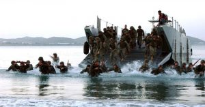
In this article, we are going to look at the five large amphibious landings from recent history, many of which took place during WWII.
5. Battle of Inchon
The Battle of Inchon was an amphibious invasion during the Korean War, resulting in a decisive victory and strategic reversal in favor of the United Nations. The operation involved some 75,000 troops and 261 naval ships, and led to the recapture of the South Korean capital of Seoul two weeks later.
The battle began on 15th September 1950 and ended four days later. The largely undefended city of Incheon was secured after being bombed by UN forces. The battle ended a string of victories by the invading North Korean People’s Army. The subsequent UN recapture of Seoul partially severed the NKPA’s supply lines in South Korea.

4. Invasion of the Philippines
On October 20th, 1944, the U.S. Sixth Army, supported by naval and air bombardment, landed on the favorable eastern shore of Leyte, one of the islands of the Visayas island group, northeast of Mindanao.
Their second major target to attack was Mindoro. This large island is directly south of Luzon and Manila Bay, and MacArthur’s main goal in taking it was to be able to construct airfields on it for fighter planes that could dominate the sky over the most important island of Luzon, with its major seaport and the capital city of Manila.
Mindoro was only lightly occupied by the Japanese Army, and much of it was held by Filipino guerrillas, so Mindoro was quickly overrun. U.S. Army engineers set about rapidly constructing a major air base at San Fabian.

Mindoro was a major victory for the 6th Army, and it also provided the major base for the next move of MacArthur’s 6th Army: the invasion of Luzon, especially at Lingayen Gulf on its western coast which were invaded on January 9th, 1945 when the first unites were lended there.
Almost 175,000 men followed across the twenty-mile beachhead within a few days. With heavy air support, Army units pushed inland, taking Clark Field, 40 miles (64 km) northwest of Manila, in the last week of January.
Two more major landings followed, one to cut off the Bataan Peninsula, and another, that included a parachute drop, south of Manila. Pincers closed on the city and, on February 3, 1945, elements of the U.S. 1st Cavalry Division pushed into the northern outskirts of Manila and the 8th Cavalry Regiment passed through the northern suburbs and into the city itself.
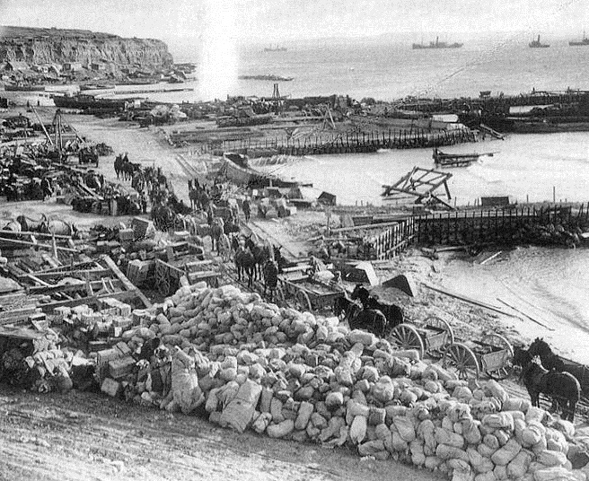
3. Gallipoli Campaign (WW1)
The Gallipoli Campaign (April-December, 1915) was the British and Allies’ attempt to capture the Dardanelles and eventually march on Istanbul, forcing the surrender of the Ottoman Empire and gaining control of the Black Sea beyond. It was the first time in modern history that a large-scale amphibious operation was ever attempted. However it is widely viewed that this campaign was mismanaged and under-committed to from the start. The most successful operation of the campaign, in fact, was the evacuation.
Gallipoli is the long strip of land that runs across from the North-Western tip of the European side of Turkey. Both these sides of the Dardanelles were heavily defended by Ottoman forts and guns. It was Winston Churchill, First Lord of the Admiralty, that proposed the plan to take Istanbul. The initial attempt was a naval assault.
The British sent a force, comprised of many old and outdated warships, to take the straights, but to no avail. The next attempt was by land and so British (including Canadians and Indians), French, Australian, and New Zealand troops were shipped out to Gallipoli.
British ships bombarded the tip of the peninsula, pulverizing Ottoman forts, but losing the element of surprise. The Turkish and Arab troops shored up their defenses with high ground, trenches, machine guns and barbed wire set in the water.
The British and French landed at Cape Helles, the most Southern point, and the Australian and New Zealand Army Corps (Anzac) landed on what became known as Anzac Cove, a few miles to the North on the Aegean side of Gallipoli to cut of the Ottomans and meet the other divisions in the middle. But by the end of the day, the Allied forces had hardly made it off the beaches, and 5,000 troops were killed or wounded.
From that day onward, the campaign was a bloody stalemate. The last attempt to break this came in August. The Sari Bair Offensive, which was spearheaded from Anzac Cove, succeeded in pushing several miles inland before the Ottomans finally overcame the weary and few men were left after the haphazard assault.
The British and French would finally leave Cape Helles in early January 1916.
The full-scale evacuation of troops began on December 15th. This only happened by night, starting with supports and reserves, and then thinning out the trenches. By December 19th, 36,000 troops were evacuated out to sea, and only 10,000 remained.
That night, the remaining troops snuck off. On their way out, many set rifles and explosives on innovative timing devices and planted grenades and mines to both make the Ottomans think they were still there and to harass them with booby traps when they did finally come to inspect the abandoned trenches.
At 4:10 AM on December 20th, Anzac Cove and Sulva Bay were empty, without a single casualty. Though it is thought that the Ottomans were totally deceived by White’s plan, it is entirely possible that Mustafa Kemal, the Turkish General in Gallipoli, was willing to let the Allies slip away, as the campaign caused thousands of casualties among his troops.
By the end of the Gallipoli Campaign, the Allies had suffered well over 100,000 casualties, and the Ottoman Empire roughly double that.
2. Battle of Okinawa
Many still think that Operation Neptune, or perhaps D-Day, was the largest of the amphibious landings to take place in history. However, if a head to head statistical analysis is made, it becomes quite clear that the largest Amphibious landing took place when Nazi Germany was almost completely beaten.
The Battle of Okinawa was fought in the Pacific Theater between the Allies, spearheaded by the US, and forces from Japan. Also known as Operation Iceberg, the Battle was made up of a string of skirmishes in the Ryukyu Islands, whose center was the island of Okinawa.
On 1st April 1945, the Allies launched a full on amphibious assault on the islands with the aim to defeat the Japanese at Okinawa.

The battle is one of the fiercest and bloodiest in the entire Pacific campaign due to the striking intensity of Japanese Kamikaze attacks and numerical strength of Allied warships, armored vehicles, and ground troops. For 80 days, reinforcements were landed on the Allied side who had effectively cut off all routes to the island for the Japanese, which was thus unable to reinforce or resupply their troops. The last remains of Japanese resistance ceased on 21st June.
The losses incurred during the battle made the US high command reconsider all plans for a Japanese mainland invasion. The US lost almost 20,000 men while the Japanese lost over 77,000; in addition, the Allies lost dozens of ships, hundreds of aircraft, and a large number of tanks.
1. D-Day Landings In Normandy
The Normandy Landings, code-named Operation Overlord, was one of the most decisive Amphibious Assaults in modern history. The landings commenced on 6th June 1944 and started the liberation of Western Europe.
While the Battle of Okinawa involved more ground troops, landing on the beach-heads, Operation Overlord is often seen as more significant, having a greater impact in history that Okinawa.

The Allied forces consisted of a total of 156,000 men compared to almost 50,000 Germans with support from 170 coastal guns. Hitler, anticipating such an assault ordered Field Marshall Erwin Rommel to take command of the German forces in 1943 and build the Atlantic Wall to thwart attempts by the Allies to retake France, Belgium, The Netherlands or Norway.
Right before the landings began, a massive airborne assault targeting the German batteries and defenses on the shore was executed and, at midnight, thousands of airborne troops landed deep behind enemy lines.
The amphibious landings began at 0630 on target beaches that were divided into 5 sectors; Utah and Omaha for the Americans, Gold and Sword for the Brittish and Juno for the Canadians. The men landing at Utah, Sword and Gold faced slightly lighter resistance than expected, but on Juno and on Omaha the Germans made the Allies pay a heavy price for every inch they gained.
This was the most decisive invasion during World War II, opening the way for a counter-offensive against the Nazi German occupation of Allied countries in Western Europe.