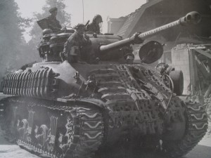

The Sherman Firefly was a World War II British variant of the Sherman tank, fitted with the powerful British 17 pounder anti-tank gun as its main weapon. Originally conceived as a stopgap until future British tank designs came into service, the Sherman Firefly became the most common vehicle with the 17 pounder in World War II. Three different variants of Sherman Firefly served during the Second World War, each based on different variants of the M4 Sherman. The Firefly conversion was carried out on Sherman I (M4), Sherman I Hybrid (M4 Composite) and Sherman V (M4A4) tanks. Some sources state that several Sherman IIs (M4A1) were converted and used in action, but photos allegedly showing these conversions are in fact views of the front half of Sherman I Hybrid Fireflies (source : Wikipedia) Thanks to our friends at the.shadock.free.fr
| US designation | British designation |
| M4 Sherman | Sherman Ic |
| M4 Composite Sherman | Sherman Ic Hybrid |
| M4A4 Sherman | Sherman Vc |
Other changes that are common to the Firefly and British Shermans are :
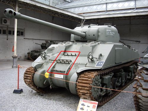
-fittings for additional tracks, that can be placed either on the front or sides of the hull
-fire extinguishers clamps, located at the back of the hull, beside the engine deck plates
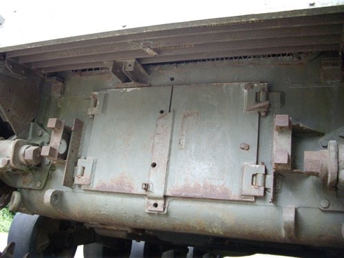
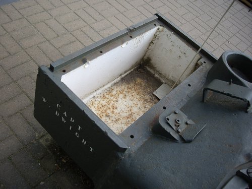
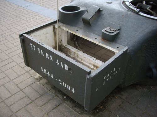
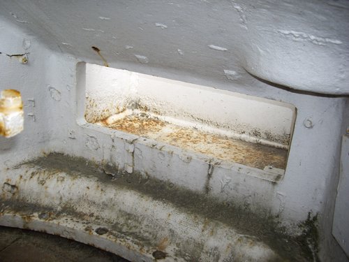
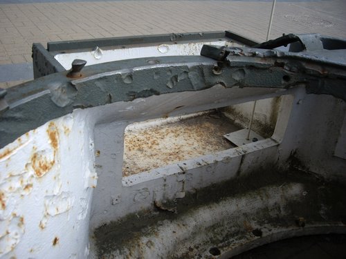
-an additional large box to the back of the hull
-smoke generators placed on the back engine doors
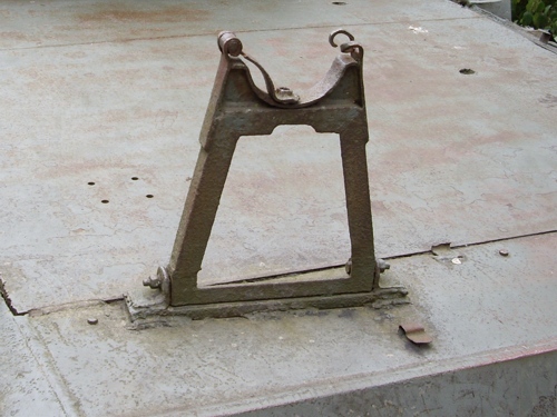
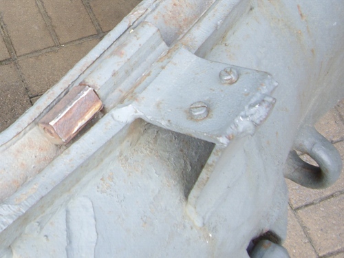
-mounts for a leaf spring that held the towing pintle
-additional towing lugs, fitted for lashing down to landing craft when deep wading trunking is fitted (as this item obscured the original towing eyes)
(Information from Kurt Laughlin and Adrian Barrel)
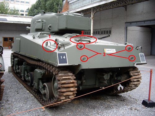
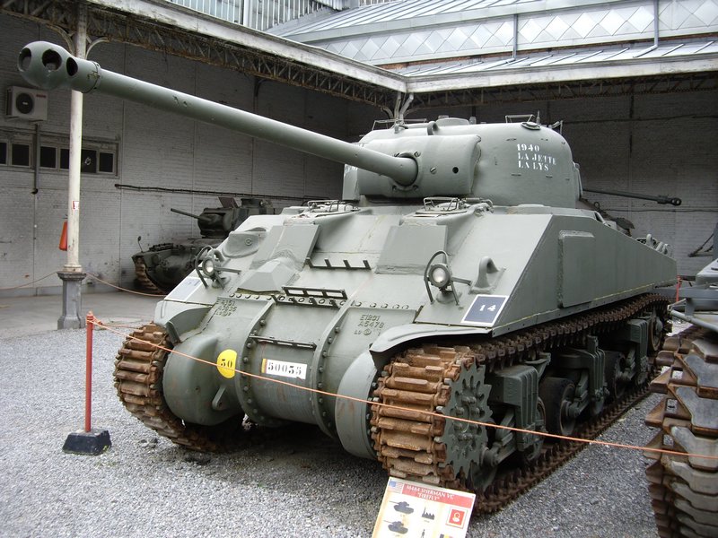
The left-side photo above shows a fire extinguisher clamp (#1), the additional gun travel lock (#2) and the fittings for the additional box (#3).
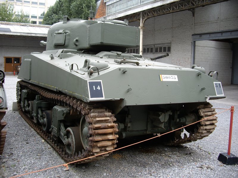
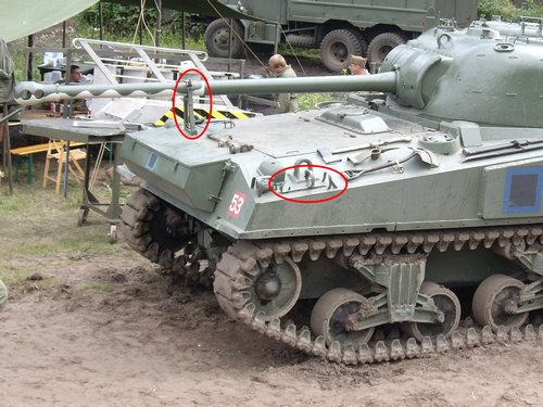
The right-side photo shows the smoke generator (#1), the mounts for a leaf spring that held the towing pintle (#2) and one of the additional towing lugs (#3).
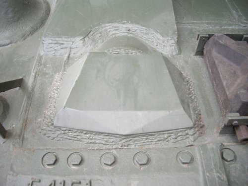
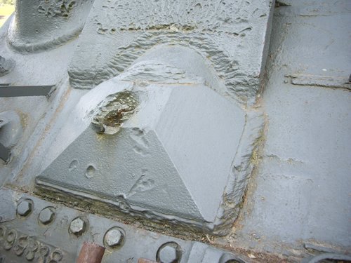
Two photos showing differrent models of armour plates that cover the bow machine gun. This piece of armour was welded to the hull, because the hull gunner was eliminated to get more room for additional 17 pounder ammunition, which was significantly longer than the 75 mm shell and thus took up more space.
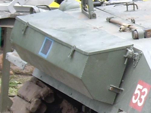
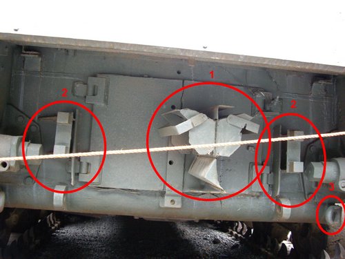
These two photos above show the additional rear box and the fittings welded to the hull to hold the box
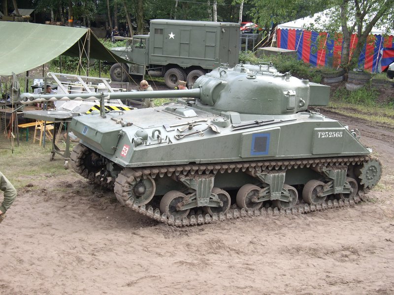
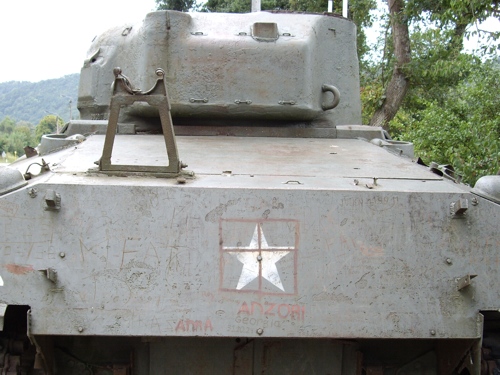
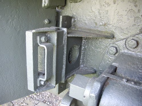
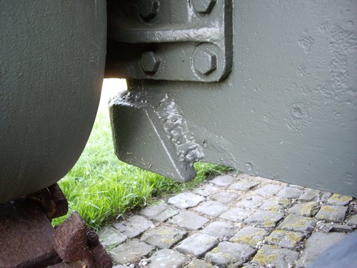
A close-up view of the additional gun travel lock. This item was placed at the rear to allow the turret to be turned back while moving. This is due to the lenght of the barrel, which reduced the mobility of the tank with the turret and barrel pointed forward
Close-up view of the mounts for a leaf spring that held an additional towing pintle. Note that the left-side photo also shows the welding of the smoke generator that was once fixed to the back engine doors
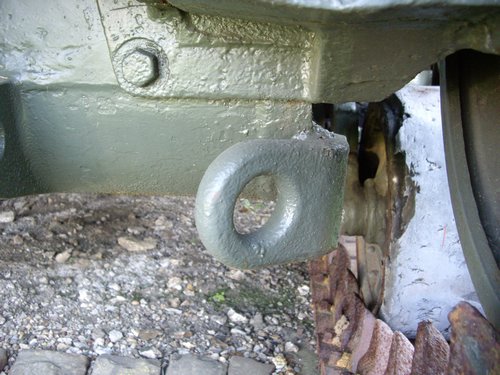
Close-up view of the additional towing lugs, fitted for lashing down to landing craft when deep wading trunking is fitted (as this item obscured the original towing lugs)
The standard M4 Sherman turret was quite heavily modified to fit with British requirements :
-The standard 75mm gun was changed with a redesigned 17 Pdr gun that had a particular recoil system, designed especially for the Sherman turret
-A new mantlet was designed to protect the 17 Pdr gun and to be fitted on a slighly modified M34A1 gun mount
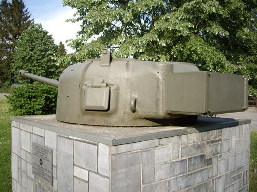
-An armoured box (a “bustle”) was attached to the back of the turret to house the radio
-A new hatch was cut into the top of the turret over the gunner’s position, because the 17 pounder’s larger breech and recoil system significantly reduced the ability of the loader to quickly exit from the tank through the commander’s hatch, if the tank was hit
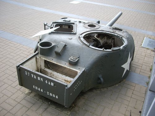
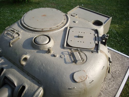
These photos above clearly show the additions/modifications that were applied to M4 Sherman turrets in order to convert them as Firefly turrets.
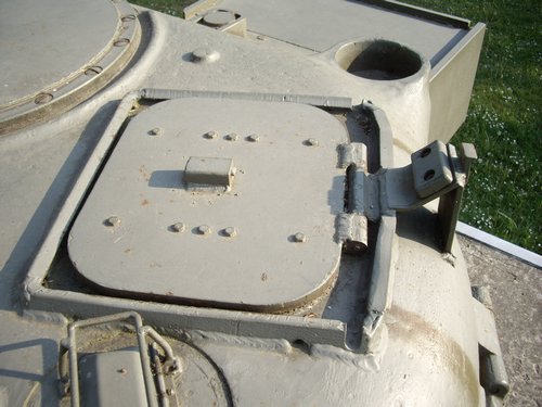
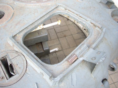
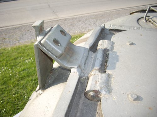
Some photos of the loader’s hatch, that show the particular hinge and shock absorber added by the Brits.
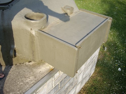
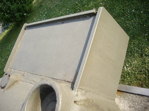
These pictures show how the armoured box (a.k.a. the “bustle”, which contains the radios) is constructed, and how the access to the radios is done through the original bustle ofd the Sherman turret. The sides from the box are 51mm thick , and the rear is 62mm thick. Top plates come in different versions , some have rounded discs welded on top, others bolted on square plates, and plane ones.
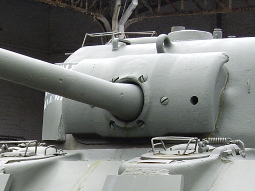
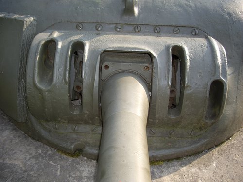
These two photos show the specific mantlet, which is different from the standard M34A1 mantlet, and the slighly modified M34A1 gun mount (with an enlargened opening for the barrel).
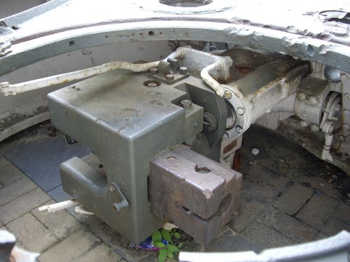
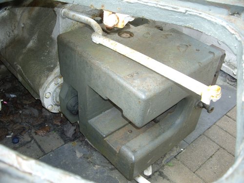
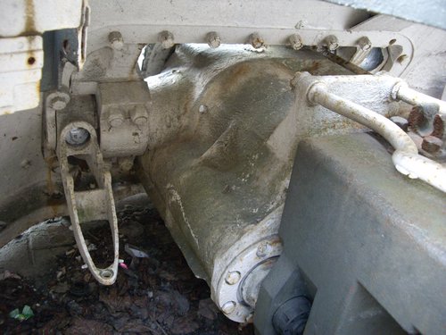
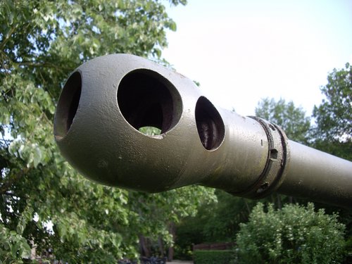
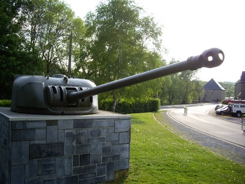
These photos show the gun breech and the specific recoil system that was created to be able to house the 17 Pdr in the Sherman standard 75mm turret. The last photo shows the typical 17 Pdr muzzle brake.