The aforementioned fan was the only casualty in the recovery as a blade broke off as we unloaded in my yard. Due to the size of the engine, the fan sticks through the floor and is normally protected by a large armoured casting but that was missing.
 I did keep the broken blade and it later welded back on with no problems. There were other little annoyances. The drivers hatch and the cupola doors had been removed in the past by cutting chunks out of the hull and ring.
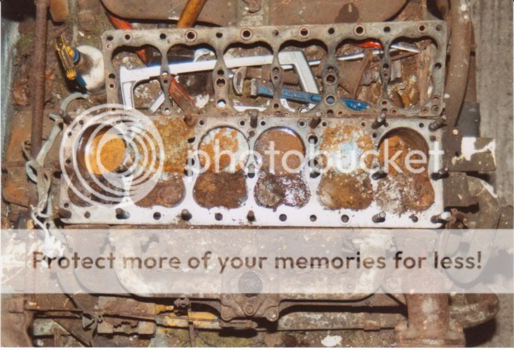
With the engine out, I pulled a head off for a look….it was not good. Some of the pistons had disolved!
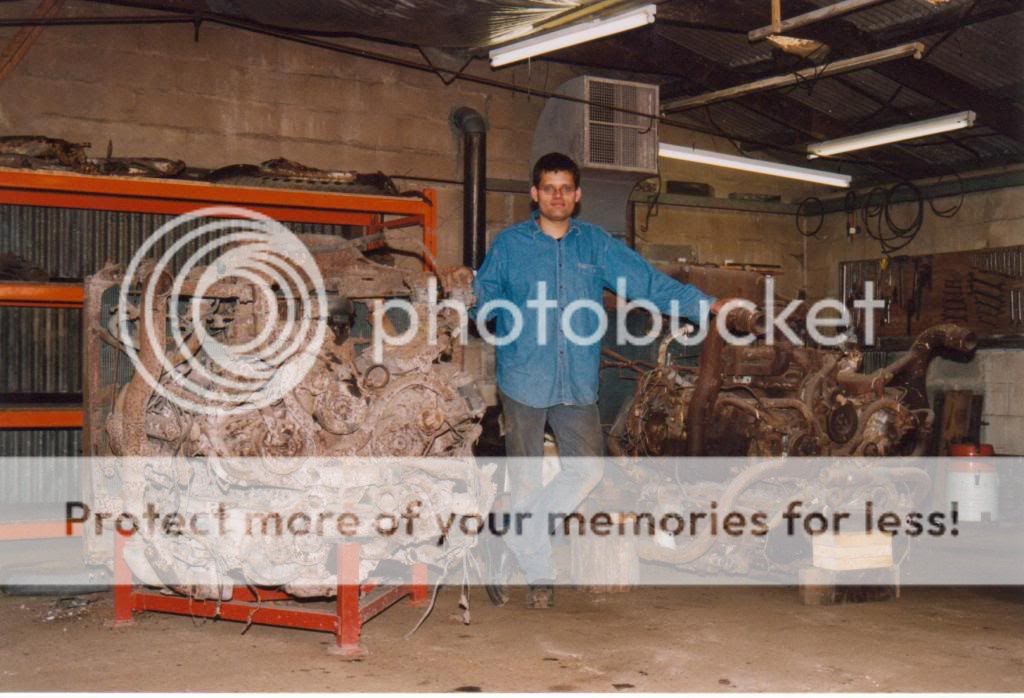
Eventually, by May 1999, I was ready to start restoring an engine. I had decided to try an engine first as i didn’t want to get the tank restored and then find I couldn’t do an engine. The Multibank is not exactly easy to lay your hands on! I did have a radial to fall back on if needed.
Tanks are mighty fine things
I won’t give a detailed history of the multibank engine as the information is available elsewhere. The engine is essentially five Windsor car engines mounted together driving a common output shaft.
It came about when Chrysler were asked to develop a tank engine due to perceived shortages in the R975 radial engine which was at that time the standard medium tank engine. Ford had come up with a V8 OHV engine which was developed from a projected V12 aircraft engine and GM were using two 6-71 two stroke diesels. All but the Ford engine were developed for the M3 medium and carried over to the M4.
Over it’s production, the multibank was improved for serviceabilty and reliability. The original design had five water pumps and this was replaced fairly early on in Sherman production with a single unit. Later engines also had the five carburettors mounted in a line on top rather than on each manifold.
Design improvements also resulted in sodium filled exhaust valves being used.
Whilst the engine was essentially the side valve six used in Dodges, apart from some internals, there is very little commonality with the truck. The blocks and heads are all special, the crank rotates anti-clockwise and the cam is gear driven. Each of the five engines are also different to each other in terms of manifolds and timing gearcases.
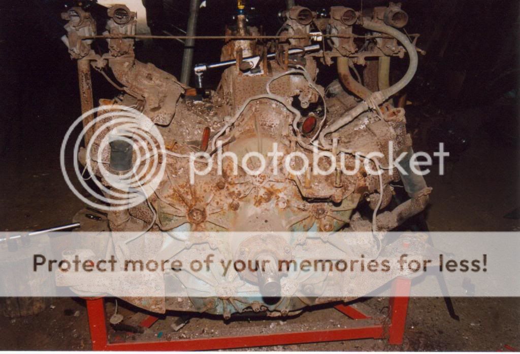
First thing to do is remove the clutch and fan. This enables you to get the radiator off. This is, of course, the reason why the radiator was still in the vehicle as it is impossible to remove it in situ!

The radiator is a big lump and whilst it was all there, I knew it would need a new core.
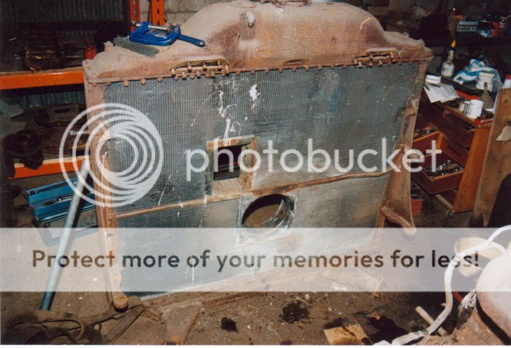
The removal of the radiator shows the drive gear case and the output shaft. Also visible is the starter motor mounting which also pokes through the radiator to engage the flywheel.
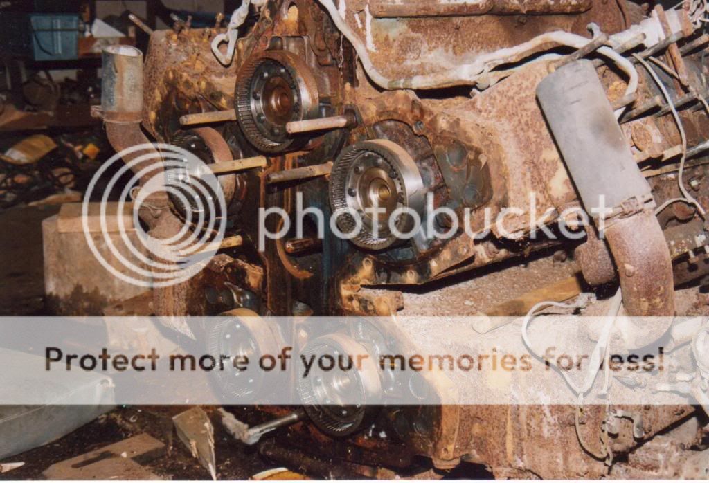
 Removing the gear case allows removal of the individual blocks but also shows quite clearly how the drives come together from each crankshaft.
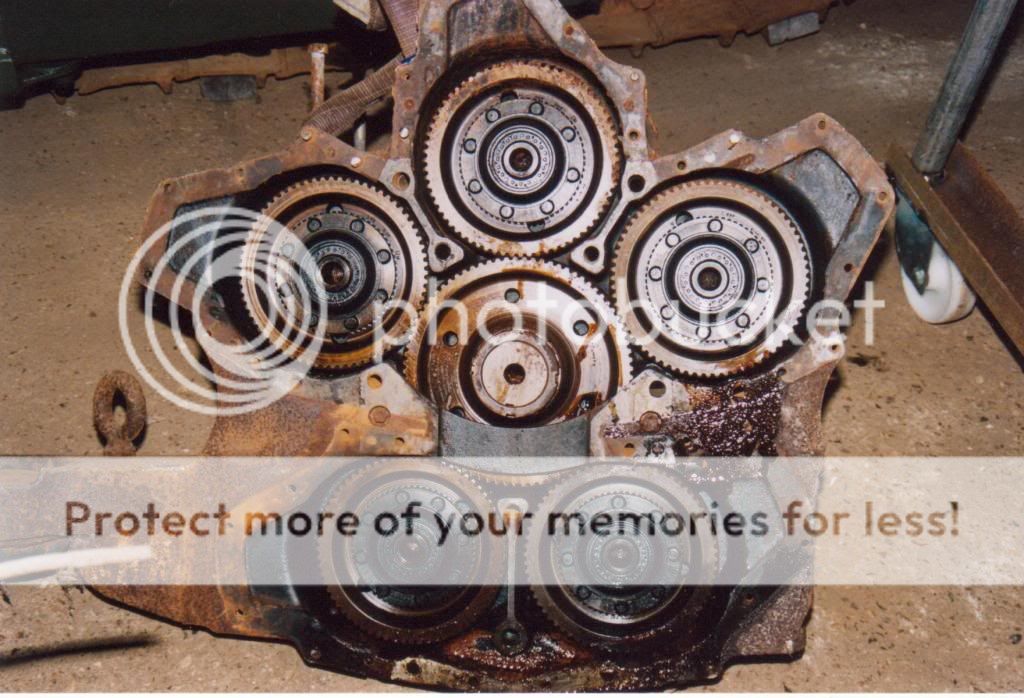
This being the inside of the casing. Each engine drives a herringbone gear which meshes with a slightly larger centre gear to give a small reduction. The centre gear drives the clutch but also the oil and water pumps through a shaft facing back through the centre block. You can also see the broken rh mounting where the side of the tank was pushed in.
This shows the front of the blocks with the coupling sleeve on each crank.